GNSS Positioning - A Reviser
Introduction
This article reviews the core principles underpinning the global navigation satellite system (GNSS). It references some of the key terminology, outlines the main potential sources of error, and describes how the application of RTK DGPS techniques can mitigate these errors to a large extent. See also Glossary of GNSS Terms and Abbrevations.
The term GPS or Global Positioning System is used generically but, as of 2023, there are four global satellite navigation constellations and two regional constellations:
- GPS - USA
- GLONASS - Russia
- Galileo - Europe
- Beidou - China
- NavIC (aka IRNSS) - India (regional)
- QZSS - Japan (regional)
There are, in addition, a number of 'augmentation systems' which use ground-based stations to augment the data provided by GNSS satellites.
In essence, GNSS is based on the principle of trilateration*, whereby a location in 3-dimensional space can be calculated by measuring the precise distances to at least 4 other non-coplanar points in space whose positions are known (the GNSS satellites). This is easier to visualise in 2-dimensions, where 3 points are necessary to establish a position.
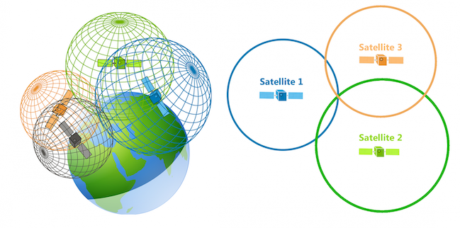
To establish the receiver's position, GNSS needs to determine:
* Trilateration measures distances; triangulation measures angles. The illustration above is somewhat simplified. In the context of GNSS, the principle is more properly referred to as 'multilateration' and is based on the convergence of cones rather than spheres.
Determining the Location of each Satellite
Most (but not all) GNSS satellites fly in medium Earth orbit (MEO) at an altitude of between 19,140 km and 23,222 km above mean sea level (HMSL). Each satellite circles the Earth twice a day. The satellites in the GPS constellation, for example, are arranged into six equally spaced orbital planes surrounding the Earth, and every plane contains four "slots" occupied by baseline satellites. This 24-slot arrangement ensures users can view at least four satellites from virtually any point on the Earth's surface.
Some GNSS satellites (e.g. in the Beidou & QZSS constellations) occupy geostationary (GEO) or inclined geostationary (IGSO) orbits, at an altitude of approximately 36,000 km.
The means to determine the current position of each satellite in a given GNSS constellation are defined in a series of four datasets:
A. Ephemerides
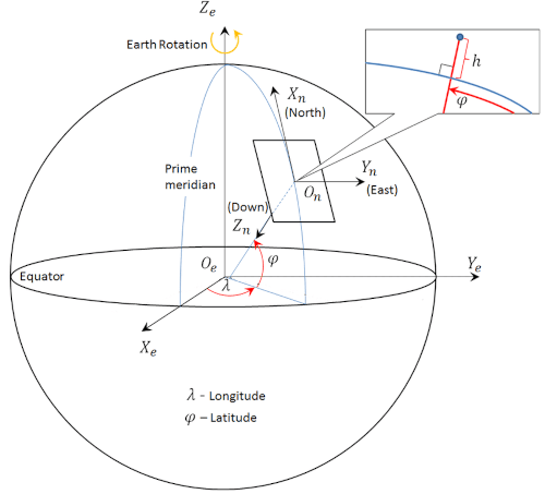
The ephemerides describe, for each satellite in the constellation, various orbital parameters which allow the receiver to calculate the precise coordinates of the satellite at any moment. The parameters are based on the right ascension (RA) system of coordinates and the earth-centered, earth-fixed (ECEF), World Geodetic System 1984 (WGS84) datum. The receiver will typically convert the ECEF solution to latitude ψ, longitude λ and height h (LLH) or North East Down (NED) relative to an ellipsoidal Earth model. The height may then be further converted to height relative to the geoid, which is essentially mean sea level. The ephemerides include:
Keplerian Parameters (classical orbital elements or COE)- Size or 'semi-major axis' of the orbit α or A (alpha, typically represented as its square root √A) (√meters)
- Shape or 'eccentricity' of the orbit e (dimensionless)
- Plane of the orbit, or 'longitude of the ascending node'/'right ascension' Ω (upper-case omega)
- Inclination i (semi-circles)
- Argument of the perigee ω (lower-case omega) (semi-circles)
- Mean anomaly M₀, which describes the angular position along the orbit (semi-circles)
- Vernal point ♈︎ (the zodiac symbol for Aries) represents the reference direction
- Δn (delta n) - Mean motion difference from computed value (semicircles/second)
- Ω˙ (omega dot) - Rate of change of right ascension (semicircles/second)
- i˙ (i dot) - Rate of change of inclination (semicircles/second)
- Cus - Amplitude of the sine harmonic correction term to the argument of latitude (radians)
- Cuc - Amplitude of the cosine harmonic correction term to the argument of latitude (radians)
- Cis - Amplitude of the sine harmonic correction term to the angle of inclination (radians)
- Cic - Amplitude of the cosine harmonic correction term to the angle of inclination (radians)
- Crs - Amplitude of the sine harmonic correction term to the orbit radius (meters)
- Crc - Amplitude of the cosine harmonic correction term to the orbit radius (meters)
The ephemerides are timestamped with the Issue of Data, Ephemeris (IODE).
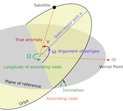
Source: ResearchGate, with modifications
B. Almanac
The almanac contains information which allows the receiver to locate the satellites in the constellation. It is essentially a simplified, coarser version of the ephemerides which is valid for a longer period of time. The age of the almanac data determines how quickly a satellite can locate the requisite number of visible satellites - the 'time to first fix' (TTFF). If the data is current or recent, the receiver can perform a hot or warm start and achieve a TTFF in less than 30 seconds. If the data has expired, the receiver must perform a cold start which may take 12.5 minutes or more, for reasons described below.
The almanac is bundled with the unique identification code or 'PRN' of each satellite (see PRN below)
C. Clock and Satellite Health Factors
This contains GPS week, age of data, satellite accuracy and health, satellite clock correction coefficients timestamped with the Issue of Data, Satellite (IODS), Issue of Data, Clock (IODC), etc.
Clock Parameters- t0e - Reference time, ephemeris parameters (seconds)
- t0c - Reference time, clock parameters (seconds)
- af0 - Polynomial coefficient for clock bias (seconds)
- af1 - Polynomial coefficient for clock drift (seconds/second)
- af2 - Polynomial coefficient for clock drift rate (aging) (seconds/second²)
D. Atmospheric Factors
This contains data which allows the receiver to model the effects of the ionosphere on the transmitted radio signal (see Ionospheric Delay below).
Ionospheric parameters- α0 (seconds)
- α1 (seconds/semi-circle)
- α2 (seconds/semi-circle²)
- α3 (seconds/semi-circle³)
- β0 (seconds)
- β1 (seconds/semi-circle)
- β2 (seconds/semi-circle²)
- β3 (seconds/semi-circle³)
The NAV Message
These four datasets are transmitted by the satellite in a series of 'frames' known collectively as the NAV message. In the case of GPS, for example, the NAV message comprises 25 frames of 1,500 bits each, = 37,500 bits or approximately 4.6 kB. Other GNSS constellations use different frame structures, but the principle is the same.
The measurement interval for these messages is referred to as the GNSS epoch.
Since the accuracy of some aspects of the information included in the NAV message deteriorates with time (at a rate of roughly 4 cm/sec), it is updated on a periodic basis (every 2 hours for ephemerides, at least every 6 days for almanac) by a series of ground stations known collectively as the Control Segment.
Note that the NAV message transmission rate is only 50 bits/sec. A full set of 25 frames can therefore take up to 12.5 (37,500 / 50 / 60) minutes to transmit, or even longer if the signal is poor or intermittent. For this reason, several 'assisted GNSS' (A-GNSS) techniques have been developed to improve the time to first fix. In essence, these aim to transmit the necessary ephemerides and almanac data to the receiver via alternate faster communications channels e.g., mobile radio or internet.
Determining the Distance to each Satellite
Since it is impractical to measure celestial distance directly, GNSS deduces distance by multiplying the time it takes for a radio signal to travel from the satellite to the receiver - the 'time of flight' (tof) - by the speed of light (approximately 300,000 km/s):
Distance = speed * (time of arrival toa - time of transmission tot)
This calculated distance is known as the 'pseudorange' (RP). In mathematical terms:
RP = c ΔT
where c is the speed of light and ΔT represents the time of flight.
The time of transmission and time of arrival must be measured at the same point in the radio signal waveform - the 'phase centre'. To do this, GNSS needs accurate and synchronised time references at both ends of the transmission. The satellites themselves have extremely accurate atomic clocks, but for reasons of economy and practicality the receivers generally have simpler quartz-based clocks.
To determine the travel time (and hence pseudorange) as accurately as possible, GNSS employs a number of complementary techniques based on three key observables:
1. 'Pseudo-Random Noise' (PRN) Code
The 'pseudo-random noise' code (aka ranging code) is basically a long, non-repeating (but not strictly random - hence 'pseudo') binary waveform. Each satellite is assigned a unique PRN code and these are known to the receiver. The satellite embeds this code into the transmitted signal. By shifting or 'slewing' a replica PRN waveform generated by the receiver until it correlates with the original PRN transmitted by the satellite, the travel time or ΔT can be deduced.
Two types of PRN or ranging code are in common use:
- C/A or Coarse/Acquisition (sometimes Civilian Access) code; a 1023-chip code transmitted at 1.023 Mchips/sec. Used for mainstream GNSS applications. “chip” is a term used in digital telecommunications to denote a single pulse of data. A "symbol" is comprised of one or more chips and the symbol rate per second is referred to as the baud rate.
- P or Precision (sometimes Protected) code, a much longer 6x10¹²-chip code transmitted at 10.23 Mchips/sec (10 times faster than the C/A code). It was traditionally reserved for military use. The code is encrypted to prevent spoofing, the encrypted version being referred to as P(Y).
2. Carrier Phase
Besides the PRN ranging codes, the carrier wave phase itself can also be used to obtain a measure of the apparent distance between satellite and receiver. These carrier phase measurements are much more precise than the code measurements (by up to two orders of magnitude), but they are ambiguous by an unknown integer number of wavelengths (λN) - the so-called 'integer ambiguity' problem. This ambiguity changes arbitrarily every time the receiver loses the lock on the signal, producing jumps or range discontinuities.
Ranging code and carrier phase measurements can be characterised thus:
- Ranging code measurements are noisy but unambiguous.
- Carrier phase measurements are precise but ambiguous.
3. Doppler Shift
Since the satellites are in constant motion relative to the receiver, the apparent frequency of the signal changes due to the phenomenon of Doppler shift. The Doppler shift provides the means to enhance a number of GNSS computations, but perhaps the most important application of Doppler data is the determination of the range rate between a receiver and a satellite. Range rate is a term used to mean the rate at which the range between a satellite and a receiver changes over a particular period of time. This can in turn be used to mitigate some of the sources of error in carrier phase measurement.
The Doppler shift is primarily determined by the relative velocity of the satellite's and receiver's antennas, plus a common offset that is proportional to the receiver's clock frequency error.
GNSS Signal
The original GPS design utilised two L band carrier wave frequencies, denoted L1 and L2:
- L1 1575.42 MHz - used for C/A and P(Y) codes
- L2 1227.60 MHz - used for P(Y) codes
Subsequent GNSS constellations use a range of frequencies in the L band:
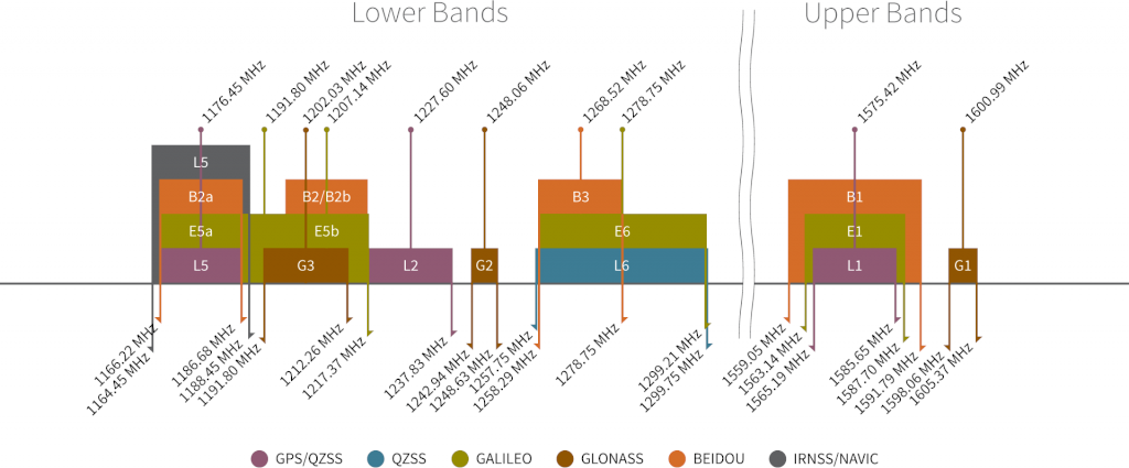
ⓘ Besides redundancy and increased resistance to jamming, a critical benefit of having two frequencies transmitted from one satellite is the ability to measure directly, and therefore remove, the ionospheric delay error for that satellite (see Ionospheric Delay below).
The C/A, P(Y) and NAV data are modulated onto the sinusoidal carrier wave using a technique known as binary phase-shift keying (BPSK), the same technique as used in Wi-Fi and Bluetooth signals.
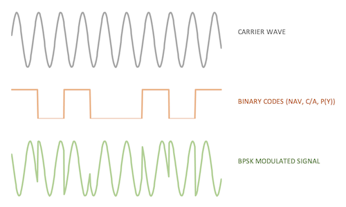
The modulated signal is received and decoded by the receiver.
Sources of Errors
ⓘ GNSS measurements are subject to a number of errors which can, unless corrected or otherwise mitigated, reduce the accuracy or reliability of the navigation solution.
1. Dilution of Precision
Ideally, the satellites used for position calculation should be widely spaced to achieve the greatest measurement precision. The effect of geometry (the relative positions of the satellites and receiver) on the distance measurement is known as 'dilution of precision' (DOP).
DOP can be expressed as a number of separate measurements:
- HDOP - horizontal dilution of precision
- VDOP - vertical dilution of precision
- PDOP - position (3D) dilution of precision
- TDOP - time dilution of precision
- GDOP - geometric dilution of precision
DOP cannot be corrected as such but can be mitigated by having the best (broadest) possible view of the sky.
2. Multipath Effects
In radio communication, multipath is the propagation phenomenon that results in radio signals reaching the receiving antenna by two or more paths. Causes of multipath include atmospheric ducting, ionospheric reflection and refraction, and reflection from water bodies and terrestrial objects such as mountains and buildings. When the same signal is received over more than one path, it can create interference and phase shifting of the signal. Destructive interference causes fading; this may cause a radio signal to become too weak in certain areas to be received adequately. For this reason, this effect is also known as multipath interference or multipath distortion.
Some GNSS receivers can be configured to ignore satellite signals from certain directions to mitigate multipath effects.
3. Receiver Noise
The receiver code noise is a white-noise-like error and can be smoothed electronically using a low pass filter. The carrier-to-noise ratio is referred to as the CNR or CNo.
This error affects both the ranging code and carrier phase measurements, but in different magnitude. The accuracy of pseudorange measurements is about 1% of the wavelength ("chip") or better. This implies a deviation of about 3 m for the C/A code and about 30 cm for the protected P(Y) code. However, when smoothing the code with the carrier phase, the deviation due to C/A code noise can be reduced to about 50 cm.
The carrier phase noise is at the level of few millimetres (about 1% of the carrier wavelength).
Code and carrier phase noise depends on the signal strength, which varies with the elevation angle.
4. Instrumentation delays - Code and Phase Bias
GNSS hardware code and phase biases occur because of imperfections and/or physical limitations in GNSS hardware. The biases are a result of small delays between events that ideally should be simultaneous in the transmission of the signal from a satellite or in the reception of the signal in a GNSS receiver. Moreover, hardware-induced biases differ between different signals, e.g., P1 and P2, and between different carrier waves, e.g., L1 and L2. Hardware-induced biases affect, for example, estimates of the precise Total Electron Content (TEC) in the ionosphere, which in turn will cause degradation in the accuracy of the positioning solution if not handled properly.
3. Clock Offsets and Relativistic Adjustments
The clocks used in the satellite and receiver are not perfectly aligned and are themselves imperfect. Such discrepancies are important when a nanosecond represents approximately 30 cm.
In addition, the rate of advance of two identical clocks, placed one in the satellite and the other on the terrestrial surface, will differ due to the difference of the gravitational potential (general relativity) and to the relative speed between them (special relativity). This difference can be split into:
- A constant component that only depends on the nominal value of the semi-major axis of the satellite orbit, which is adjusted by modifying (in factory) the clock oscillating frequency of the satellite.
- A periodical component due to the orbit eccentricity, that must be applied by the receiver's software.
5. Orbital Errors
The orbits of the satellites are affected by many factors including variations in gravity, drag, and tidal forces from the sun, the moon, etc.
6. Tropospheric Delay
The troposphere is the lowest layer of the Earth's atmosphere, extending from the surface to an altitude of about 18 km and containing 99% of the atmosphere's water vapour.
The effect of the troposphere on the GNSS signal appears as an extra delay in the measurement of the signal traveling from the satellite to receiver due to slight variations in the speed of light through aqueous media. This delay depends on the temperature, pressure, humidity as well as the transmitter and receiver antennae location.
7. Ionospheric Delay
The ionosphere is the atmospheric layer that extends from an altitude of 48 km to more than 960 km. It contains a partially ionised medium, as a result of the X and UV rays of solar radiation and the incidence of charged particles.
The propagation speed of the GNSS electromagnetic signal in the ionosphere depends on its electron density, denoted Total Electronic Content or TEC. This is typically heightened during the day and lessened overnight.
As the ionosphere is a dispersive media, the GNSS signal's refraction depends on its frequency (as the squared inverse). This relationship to signal frequency allows us to remove up to 99.9% of its effect by using two carrier frequencies (e.g., L1 & L2). Single frequency receivers must apply an ionospheric prediction model to remove (as much as possible) this effect, which can reach up to several tens of meters.
The Pseudorange Equation
The complete pseudorange calculation can be expressed as follows:
RP = ρ + dρ + c(dt-dT) + dion + dtrop + ϵmp + ϵ p
where:
- RP = pseudorange measurement
- ρ (rho) = true range
- dρ = satellite orbital errors
- c = speed of light
- dt = satellite clock offset from GPS time
- dT = receiver clock offset from GPS time
- dion = ionospheric delay (re. TEC)
- dtrop = tropospheric delay
- ϵmp = multipath effects
- ϵp = receiver noise
Indicative Error Magnitudes
Errors which affect pseudorange estimation are collectively known as User Equivalent Range Errors (UERE). While it is difficult to quantify such errors exactly, the following table gives a broad indication of relative magnitude:
| Error Source | Indicative Magnitude (m) |
|---|---|
| C/A Code Noise | 3 |
| P(Y) Code Noise | 0.3 |
| Ionosphere Effects (TEC) | 5 |
| Orbital Errors | 2.5 |
| Satellite Clock Errors | 2 |
| Multipath Distortion | 1 |
| Troposphere Effects | 0.5 |
Error Correction - High Precision GNSS Technologies
Overview
Traditional GNSS technology is capable of providing a navigation solution accurate to around 2.5 metres with clear line of sight, and perhaps 5-15 metres in urban, forested or mountainous areas.
However, technological advances over the past couple of decades have enhanced the ability of GNSS to correct for the various errors and achieve (in the right circumstances) cm-level precision. These advances include:
- More powerful GNSS receiver processors
- The availability of new GNSS signals and compatible multi-band receivers, including the newer L5 and L6 bands
- The availability of more sophisticated wide range GNSS reference station networks
High precision GNSS correction technologies can be broadly categorised into Observation Space Representation (OSR) and State Space Representation (SSR).
- Observation Space Representation (OSR) - established technologies which involve the comparison of observations by the user's GNSS receiver and a calibrated fixed-base reference station to provide 'corrections' via a two-way Internet or satellite link. Examples of OSR techniques include Differential GPS (DGPS) and conventional Real Time Kinematics (RTK e.g. NTRIP).
- State Space Representation (SSR) - newer technologies which involve large networks of reference stations covering a broad geographical area which provide various "state space" parameters (including satellite clock, orbit and biases and possibly atmospheric measurements) to any GNSS receivers within their coverage area via a one-way Internet or satellite link. These parameters allow suitably-equipped receivers to apply 'corrections' to their own observations. Examples of SSR techniques include Precise Point Positioning (PPP) and Satellite-based Augmentation Systems (SBAS).
OSR techniques are localised (to a particular fixed-based reference station) and lend themselves to applications such as topographical surveying, agriculture, topographic drones and automated public works vehicles.
SSR techniques are not localised and lend themselves to mobile applications such as automotive, public transport and delivery drones.
| Technology | Pros | Cons |
|---|---|---|
| OSR e.g. DGPS, RTK, NRTK |
Quick (less than a minute) to achieve full ("fixed ambiguity") accuracy | Requires simultaneous observations from multiple receiver stations (e.g. fixed base and rover) |
| Low processing overhead | Accuracy decreases with distance from fixed base ("baseline") | |
| Localised coverage | ||
| SSR e.g. PPP, SBAS, HAS |
Uses a single receiver | Takes more processing power |
| Wider (potentially global) coverage | Requires a continuous outside ephemeris correction stream | |
| Takes some time (up to tens of minutes) to achieve full ("fixed ambiguity") accuracy |
Some High Precision GNSS Technologies
A number of high precision GNSS technologies are available, each of which attempts to correct some or all of the errors listed above. Some commercial GNSS solutions may combine several of these technologies to improve accuracy, availability and/or convergence times.
- Differential GPS (DGPS). A collective term for a range of techniques which are essentially based on the difference between the position reported by the user's GNSS receiver and that reported by another GNSS receiver at a calibrated fixed terrestrial reference point (antenna reference point or ARP). Since atmospheric factors are often the most significant source of error, the fixed reference point should ideally be in relatively close proximity to the user's receiver, such that local atmospheric conditions are comparable (generally within a 20 km radius).
- LTE Positioning Protocol (LPP). A Networked RTK (NTRK) GNSS correction protocol transmitted via the LTE (or sometimes '5G') mobile phone network.
- Real-time Kinematics (RTK), commonly used for GIS and surveying applications. This uses measurements of the phase of the signal's carrier wave rather than the information content of the signal and relies on a single reference station or interpolated virtual station to provide real-time corrections. It essentially endeavours to resolve the carrier wave range 'integer ambiguity' problem. The improvement possible using this technique is potentially very high. For instance, in the case of GPS, the L1 C/A code changes phase at 1.023 MHz (pulse length 293 m), but the L1 carrier itself is 1575.42 MHz (wavelength 19 cm), which changes phase over a thousand times more often. If one assumes a 1% error in phase lock, this corresponds to a ±1.9 mm error in pseudorange estimation. A common implementation of RTK DGPS is the NTRIP protocol, described below.
- Post-processing Kinematics (PPK). Similar in concept to RTK, but instead of applying DGPS corrections in real-time, PPK corrections are applied retrospectively to a captured raw GNSS datastream using specialised software. Some PPK software applications (e.g. RTKLIB) support a variety of correction algorithms in multiple passes and are capable of extremely high accuracy. The raw datastream is typically converted to an industry-standard Receiver Independent Exchange Format (RINEX) format before processing.
- Satellite-based Augmentation Systems (SBAS). These support wide-area or regional augmentation of GNSS positioning through the use of additional satellite-broadcast messages. Using measurements from the ground stations, correction messages are created and sent to one or more satellites for broadcast to end users as differential signals. Examples include the Wide Area Augmentation System (WAAS), operated by the US Federal Aviation Administration, and the Quasi-Zenith Satellite System (QZSS), operated by Japan.
- Ground-based Augmentation Systems (GBAS). These provide DGPS corrections and integrity verification near an airport, providing precision approaches e.g. for runways that do not have Instrument Landing Systems.
- Precise Point Positioning (PPP). A PPP solution depends on a set of corrections generated from a network of global reference stations. Once the corrections are calculated, they are delivered to the end-user via satellite or over the Internet. These corrections are used by the receiver to improve position accuracy. A typical PPP solution requires a period of time to converge to full ("fixed ambiguity") accuracy in order to resolve any local errors such as atmospheric errors, multipath and receiver biases. The actual accuracy achieved and the convergence time required is dependent on the quality of the corrections and how they are applied in the receiver.
- PPP-RTK. A combination of PPP and RTK techniques which utilises global PPP reference station "state space" data in conjunction with local RTK data to achieve faster fixed ambiguity convergence than would be available via PPP alone. One implementation of this method is the SPARTN protocol.
NTRIP
NTRIP (Networked Transport of RTCM via Internet Protocol) is a proprietary OSR RTK protocol published by the Radio Technical Commission for Maritime Services (RTCM). NTRIP transmits correction data - typically in the form of binary RTCM messages - over the public internet using the standard Hypertext Transfer Protocol HTTP/1.1. The current version (as at January 2023) is 2.0, based on the RTCM 3.n message specification.
See Achieving cm Level Accuracy Via Real-time Kinematics for a practical illustration of the technique.
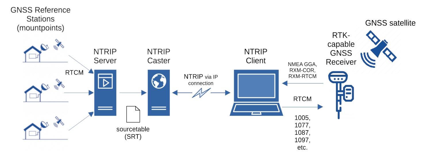
The NTRIP network comprises a series of fixed Continuously Operating Reference Stations or CORS (aka mountpoints), each of which transmits its own RTCM RTK data stream, typically at a rate of one message a second (1 Hz). An NTRIP server collates these data streams and provides a plain text list or sourcetable of the available mountpoints. Each sourcetable entry includes information on the name and coordinates of the station, which RTCM protocol is uses, which GNSS constellations it supports, which RTCM message types it transmits, and whether it requires the NTRIP client to report its current LLH position via an NMEA GGA message, e.g.:
['WEBBPARTNERS', 'Macclesfield', 'RTCM 3.2', '1005(5),1077(1),1087(1),1097(1),1127(1),1230(5)', '2', 'GPS+GLO+GAL+BDS', 'SNIP', 'GBR', '53.24', '-2.16', '1', '0', 'sNTRIP', 'none', 'B', 'N', '6820', '']
An NTRIP caster broadcasts the sourcetable and binary RTCM data over the public internet. NTRIP data may be unencrypted (HTTP) or encrypted (HTTPS). Some NTRIP casters are free, public domain services; others require authentication via userid and password.
An NTRIP client - which may be a software application (such as PyGPSClient), or integrated into firmware - parses the NTRIP data stream from the selected mountpoint and passes the RTCM messages to an RTK-capable GNSS receiver (e.g. u-blox ZED-F9P). The receiver's software then calculates the relevant adjustment to the reported navigation solution.
RTCM Message Types
The message types transmitted by an NTRIP RTCM3 mountpoint typically include:
- 1005 or 1006 - Reference station data, including ID, ECEF coordinates and (for 1006) antenna height.
- 1019, 1020, 1041-1046 - Ephemerides Data for each visible constellation.
- 107n, 108n, 109n, 110n, 111n, 112n and 113n - Multiple Signal
Messages (MSM)
representing GPS, GLONASS, Galileo, SBAS, QZSS, Beidou and NavIC respectively. These
comprise:
- A header containing GNSS epoch, IODS and clock data.
- A repeating group of rough phase range, range rate and extended satellite information; one for each satellite nSAT.
- A repeating group of precise phase range, range rate and CNR data; one for each signal (L1, L2, L5 etc.) nSIG per satellite (nSAT * nSIG = nCELL).
- 1230 - GLONASS Code Phase Bias data.
The pyrtcm Python library can be used to decode individual RTCM messages into their constituent datafields, e.g.:
<RTCM(1005, DF002=1005, DF003=2076, DF021=0, DF022=1, DF023=1, DF024=1, DF141=0, DF025=3822566.3113, DF142=1, DF001_1=0, DF026=-144427.5123, DF364=0, DF027=5086857.1208)>
where DF002 is the message type, DF003 represents the station ID (ARP) and DF025, DF026 and DF027 represent the station ECEF X,Y,Z coordinates - in this case equivalent to an LLH of 53.24, -2.16, 214.98 m.